The proposal and the development of the on-line calibration system for HEC
calorimeter is one of the crucial tasks.
In order to achieve an optimal energy resolution of the calorimeters it is necessary to develop
a system to calibrate the gain variations in the
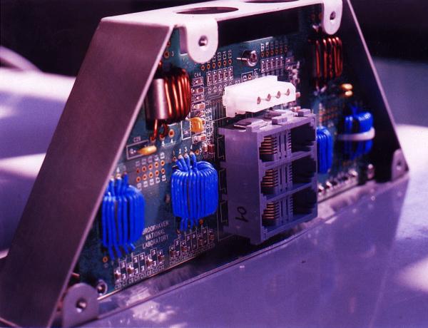
The first prototype of a calibration pulse generator was developed by our institute.
We used a specific integrated circuit (ASIC) (CMOS technology with a
structure length of 1.2
The calibration system was developed and tested several time - in 1999-2002 -
combined EMEC/HEC, and in 2003
combined EMEC/HEC/FCAL and HEC/FCAL tests.
In Fig. 1 you can see the calibration signal (left) and
the prediction for the ionisation signal (right) together with the
residuals with the respects to the fit (lower figures).
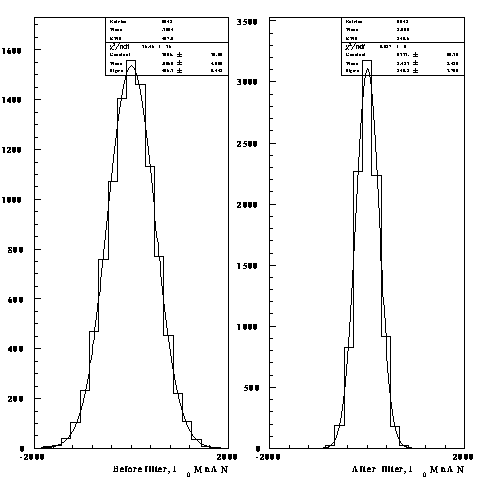
In 1998 the Cleland method for the noise suppression in the calorimeter
readout was successfully applied by our group. The improvement of the signal/noise
ratio can be seen in Fig. 2.
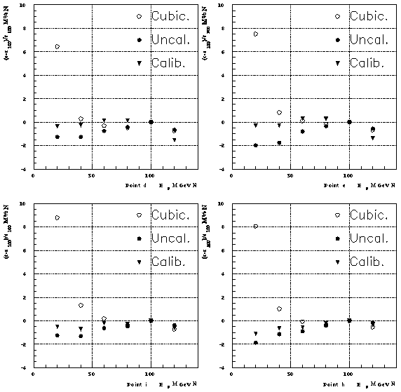
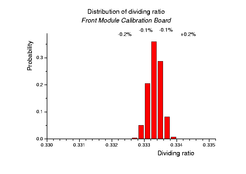
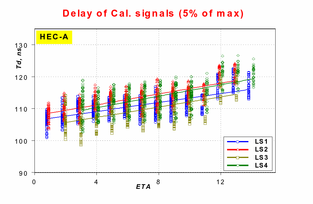
In Fig. 3 is shown the linearity in the four different impact points in
the test modules with the points corresponding to uncalibration and calibration data for the various
electrons energies. The improvement is markant.
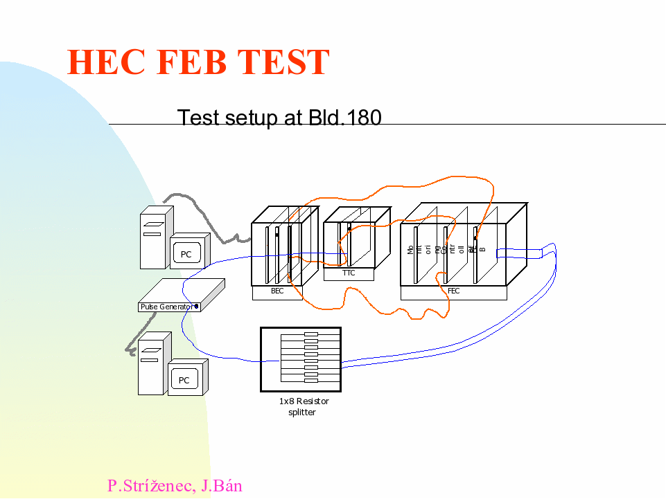
is going to be used for the EM and HEC part of the Atlas calorimeter. As described
in the TDR
of the liquid argon (LAr) calorimeter, the FEBs contain
the electronics for amplifying, shaping, sampling, pipeling, and
digitising the LAr calorimeter signals. The FEB electronics e.g. must
handle the signal dynamic range of about 16 bits without
contributing more than 0.2%.
On the Fig 5 the FEB test setup at Buld. 180 is shown.
all needed quality criteria.
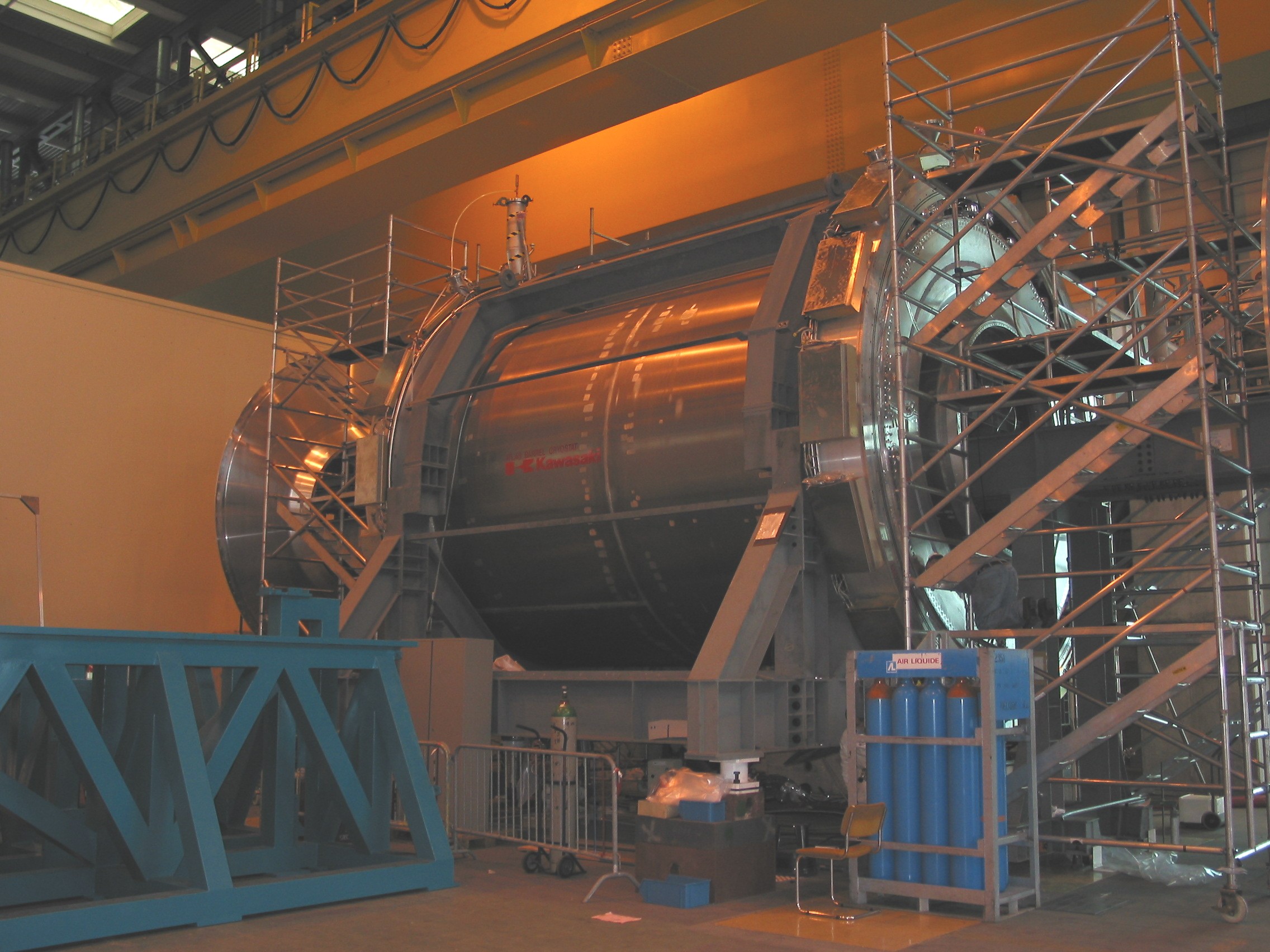
the ATLAS barrel cryostat with our filter boxes (see
Fig. 10 in more detail) is shown.
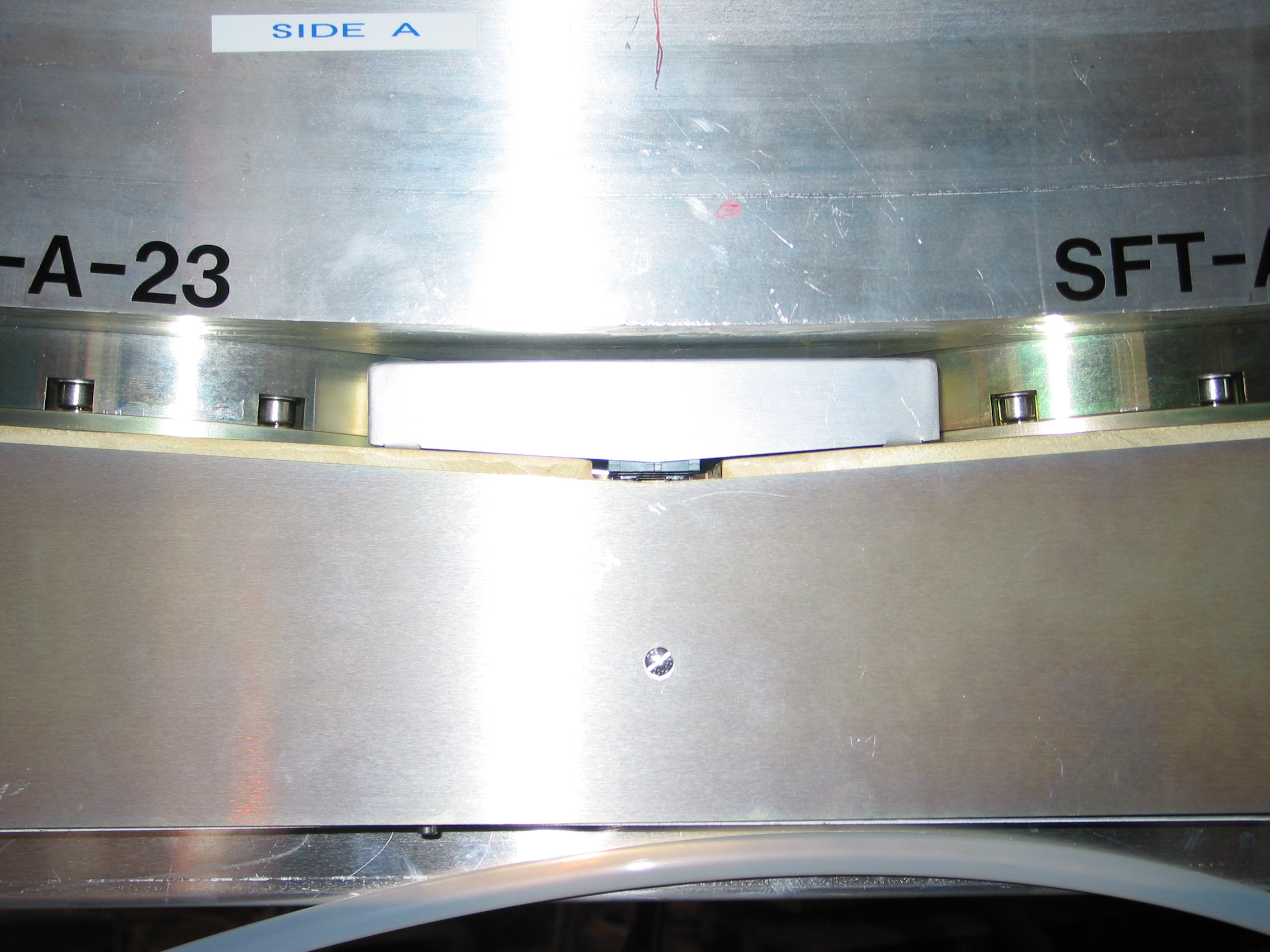
Now on the detector side, tremendous progress has been done: in building 180 for liquid argon (LAr)
HEC (for both two wheels A, and C) the cooling, testing and after than the transport to point 1
in anticipation of its imminent descent into the pit has been done also. See also Fig. 12:
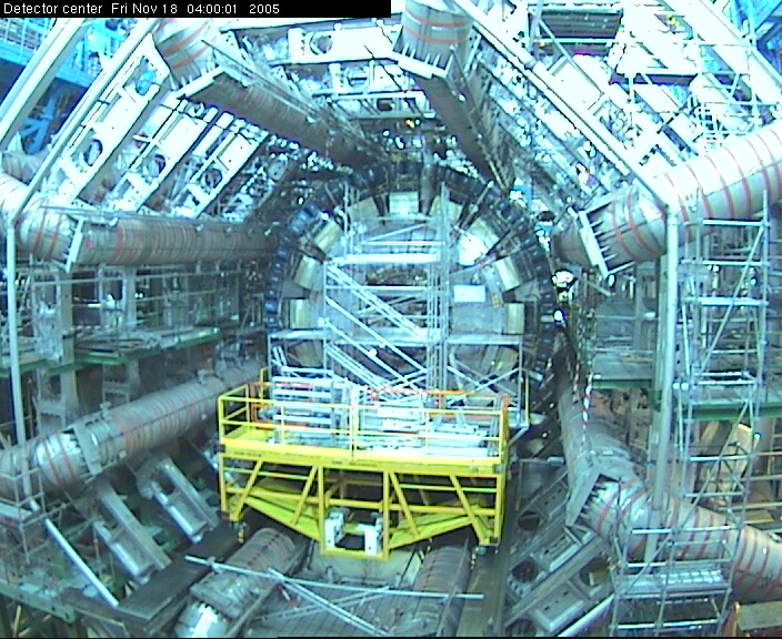
On the Fig. 13. the view into ATLAS pit with the Endcap wheels C is shown (November 2005).
190000 readout channels. Each individual channel consists of a preamplifier,
a shaper and an analog to digital converter. The calibration system has to provide reference currents
which are sent into the current sensitive preamplifiers. The shape of the current signal has to
resemble the real calorimeter signals as much as possible, with a rise time of
1 ns. Since the response of the electronics has to be known over the full
dynamic range, the calibration system has to provide currents in a range spanning five decades from
200 nA (lower value in the HEC) up to 20 mA (corresponding current produced by electrons with an
energy of 2 TeV in the electromagnetic calorimeter). The linearity of the system is required to be better
than 0.1% over the full dynamic range.
m). Our hardware was used by
Mainz group for the development of the next calibration
pulse generator model afterwards. It achieved the required characteristics because one of the main
building blocks of this
ASIC chip is a differential amplifier with automatic offset compensation. This automatic offset
compensation is essential to achieve the required linearity over the full dynamic range. To achieve
the linearity of 0.1% an offset value below 20
V has to be reached and has to be stable under operation. This also implies
that it is not affeced by the radiation which is induced during the ATLAS operation.
Over a period of ten years, for example, the calibration electronics is exposed by an integrated
neutron flux of
1013 n/cm2 with an equivalent
energy of 1 MeV (Si) and a gamma dose of 200 Gy.
Figure 1:
The calibration signal (left) and
the prediction for the ionisation signal (right) together with the
residuals with the respects to the fit (lower figures)
Figure 2:
The noise reduction for 100 GeV electron
deposits in HEC module 0 a) before and b) after filter applying
Figure 4: The view on
the FEB
Figure 5: The FEB test setup
Figure 6:
Dividing ratio of the Front Module
Calibration Distribution Boards of HEC
Figure 7:
End-Cap Cryostat after the insertion of the second HEC wheel (Dec. 2003), and
before the insertion of the forward calorimeter
Figure 8:
Filter box
Figure 9:
ATLAS barrel cryostat
Figure 10:
Detail view: the filter box in the ATLAS barrel cryostat
Figure 11:
Delay of calibration signals fro HEC-A
Figure 12:
Transport to point 1 of the End-Cap wheel C.
Figure 13:
End-Cap wheel C in ATLAS pite (November 2005)