|
The calorimeters of the ATLAS detector surround the central tracking detectors and will measure
the energy of the particles originated from the p-p interactions. In Fig. 1 a 3-dimensional view of
the calorimeters is shown.
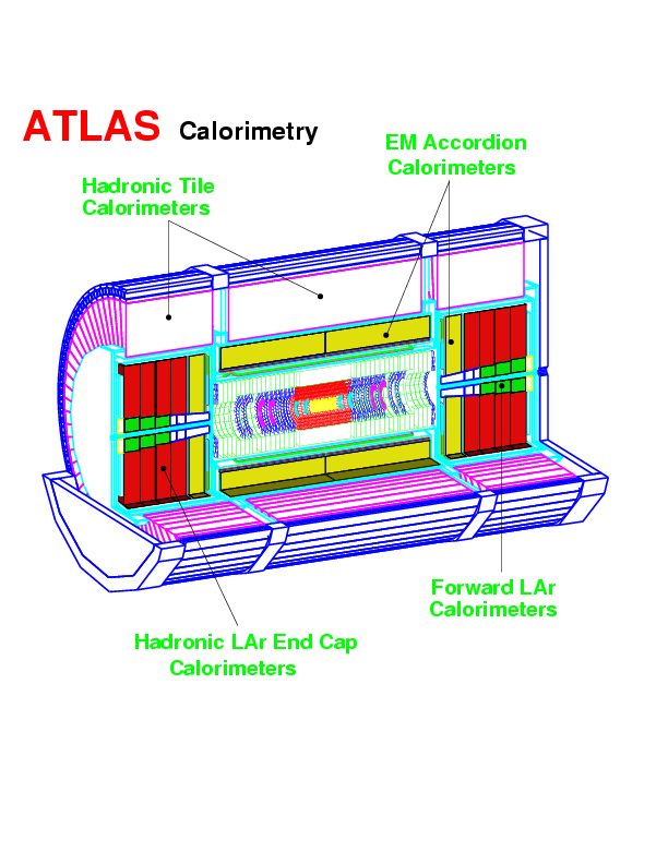
The
Hadronic End-Cap (HEC) calorimeter is designed to provide coverage for hadronic
showers in the range 1.55 < eta < 3.2. The HEC detector elements are
located in the
end-cap cryostat
at either end of the ATLAS tracking volume. It is a liquid argon (LAr) sampling calorimeter with
copper-plate absorber (with the thickness 25/50 mm).
This technology was selected as it allows a simple mechanical design to be produced that
is radiation resistant and covers the required area in a cost-effective way. 
This structure optimises the signal-to-noise ratio while reducing the high-voltage
requirements and ionisation pile-up, and limiting the effect of failure
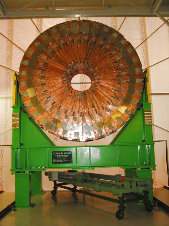
modes such as high-voltage sparks and shorts. HEC is make up from two symmetric calorimeters in the wheel structure HEC1 and HEC2, each wheel has 32 modules, see Fig. 3, where the one module of HEC is shown.

In order to determine the particle energy, the particle is stopped in the material of the calorimeter. The main fraction of the particle energy is absorbed in layers of high density material, which is Pb in the electromagnetic part (absorption of electrons/positrons and photons) and Cu (tungsten in part of the very forward calorimeter) in the hadronic part. The absorber plates are interleaved with gaps of liquid argon. The argon is ionized by the charged particles produced in the absorption process of the primary particles. An electric field is applied and the drifting electrons induce a current on the electrode structure. The total induced current is proportional to the energy of the incoming particle. The current is measured by an amplifier and is digitized afterwards.
The described type of a calorimeter is called a Sampling Calorimeter, because only a small fraction (sample) of the deposited energy is actually measured in the active medium.
Different effects contribute to the homogeneity of the signals in the calorimeter:
The Liquid Argon calorimeters are mounted in three different cryostats and cooled down to the temperature of liquid argon at a pressure of 1 bar (ca. -180 oC). HEC cold tests: totally 132 modules were cold-tested using scheme which is on the Fig 5 
and one of the result is on the Fig. 6 
One HEC wheel has roughly 4 x 7 m size. On the Fig. 7 you can see the first from four HEC wheels
Pad structure defines lateral segmentation
in (eta, phi) = 0.1 x 0.1. LAr gap is instrumented with 1 PAD board and
2 EST boards. From the electronic point of view HEC has 92 160 full
independent read-out channels, which is approximately two-time more
than in the up today largest liquid argon calorimeter which is used
in H1 in
DESY,
Hamburg. The each end-cap section contains end-cap cryostat. End-cap cryostat contains an electromagnetic calorimeter (EMEC), two wheels of one HEC, and a forward calorimeter - see Fig. 8
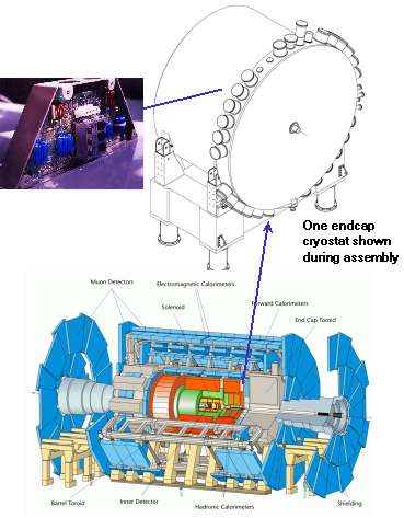
The arrow from the wheel shows on the feedthrough, which contains so called filter boxes, which had been produced by our group - see chapter 5. |